Today, 21 October, is the Day of Photonics. The date marks the day in 1983 when the General Conference on Weights and Measures fixed the speed of light at exactly 299,792,458 m/s. The European Photonics Industry Consortium (EPIC) started the Day of Photonics in 2014 to make the field more visible outside labs and companies. […]
art photonics Technical Note 007 Both polycrystalline silver halide fibers (PIR) and hollow waveguides (HWG) from art photonics transmit up to 85–90 % of CO₂ laser radiation (10.6 µm) through a 1 m high-power cable. Choose a PIR fiber when the cable must bend, move or run long distances: a full 360° loop costs only […]
art photonics will be represented at analytica China 2026 in Shanghai from 16 to 18 November 2026. Together with our local distribution partner, UniqueRay Technologies Limited (Uray), we will be presenting our specialty fiber-optic solutions for inline Process Analytical Technology (PAT) and laboratory spectroscopy at Booth # E6.6920. At art photonics, we design and manufacture […]
art photonics GmbH is currently exhibiting at the China International Optoelectronic Exposition (CIOE) 2026 in Shenzhen. From September 9-11, we are represented at this premier industry event by our partner, UniqueRay Technologies Limited. Industry professionals are invited to visit Stand 8B16 to review our advanced portfolio of specialty fiber optic solutions. UniqueRay is showcasing our […]
art photonics GmbH, founded in Berlin in September 1998, is one of the worldwide leaders in development and production of specialty fiber products for a broad spectrum from 300 nm to 16 µm. Unique technologies of Polycrystalline Mid InfraRed (PIR-) fibers and Metal coated Silica fibers are used for assembly of various spectroscopy probes for medical diagnostics and industrial process control, in volume production of fiber for medical and industrial lasers, for different fiber bundles, etc. Since January 2024 art photonics GmbH is a member of NYNOMIC GROUP.
The date marks the day in 1983 when the General Conference on Weights and Measures fixed the speed of light at exactly 299,792,458 m/s. The European Photonics Industry Consortium (EPIC) started the Day of Photonics in 2014 to make the field more visible outside labs and companies.
For us at art photonics, it is also a good day to thank the people we work with: researchers, process engineers and laser developers who take our fibers into their reactors, labs and production lines, and who regularly bring us applications that a standard fiber cannot handle.
Our corner of photonics lies beyond the red end of the spectrum. In 1800, William Herschel placed a thermometer just past the red light from a prism and measured a higher temperature than in the visible colours. It was the first evidence of infrared radiation, light that we feel as warmth but cannot see.
More than two centuries later, most of what we make in Berlin exists to bring that light to places where it is otherwise hard to measure or deliver. Our fiber-optic ATR and Raman probes are used for in-line process monitoring, our mid-IR fiber cables guide the beams of quantum cascade lasers, and our fiber delivery systems carry 10.6 µm CO₂ laser radiation. Behind all of them are our specialty fibers: chalcogenide and polycrystalline (PIR) fibers for the mid-infrared, and silica fibers for the UV to NIR range.
Happy Day of Photonics to our customers, partners and everyone working with light, in research and in industry.
art photonics Technical Note 007
Both polycrystalline silver halide fibers (PIR) and hollow waveguides (HWG) from art photonics transmit up to 85–90 % of CO₂ laser radiation (10.6 µm) through a 1 m high-power cable. Choose a PIR fiber when the cable must bend, move or run long distances: a full 360° loop costs only about 1.5 % of transmission. Choose a hollow waveguide when you need a low-divergence output beam (about 5.7° full angle) and the cable can stay fairly straight.
art photonics GmbH manufactures both technologies in-house in Berlin for high-power light delivery in the mid-infrared. They reach similar transmission when properly optimized, but they are built for different operating conditions. This article explains how each one works, compares their key parameters for CO₂ laser beam delivery, and gives a simple selection rule. Connector types (SMA, FC/PC, FC/APC), bending radii and other details are listed in the product datasheets linked at the end.
What are PIR fibers and hollow waveguides?
PIR fiber: solid-core polycrystalline silver halide fiber
A PIR fiber is a solid core/clad fiber made of silver chloride–silver bromide solid solutions (AgClxBr1−x). In art photonics PIR fiber, the core is AgCl0.25Br0.75 and the cladding is AgCl0.5Br0.5. Light is guided by total internal reflection.
PIR fibers have low bending losses and a high numerical aperture (NA). Because silver halides have a high refractive index, the bare fiber end faces would reflect part of the light (Fresnel reflection). art photonics suppresses these losses with an anti-reflective microstructure on the end faces, called SMART treatment, made during cable assembly.
Hollow waveguide (HWG): air-core silica capillary
A hollow waveguide is an air-core silica glass capillary with a reflective silver/silver iodide (Ag/AgI) coating on its inner wall. The capillary is protected by an acrylate layer and a polymer buffer. Light travels through the air core and is guided by reflection from the coated wall.
Because the core is air, an HWG has no end-face Fresnel reflection, and its output beam has low divergence. However, its transmission and beam quality depend on the coupling optics and on how much the waveguide is bent.
PIR vs HWG: key parameters at 10.6 µm (CW)
Parameter
PIR fiber
Hollow waveguide (HWG)
Core / inner diameter available
240–900 µm core (multimode)
500–1000 µm bore (multimode)
Attenuation at 10.6 µm
0.2–0.4 dB/m
0.3–0.7 dB/m
Bending loss, one full 360° loop of 40 cm diameter 1
≈ 0.05 dB
≈ 0.5–1 dB
Absolute transmission loss when bent (one 360° loop, 40 cm diameter) 1
≈ 1.5 %
≈ 14 %
How transmission is improved
Anti-reflective microstructures on the fiber end faces (SMART treatment, made during cable assembly)
Coupling optics with the optimum f-number (NA)
Transmission of CO₂ laser radiation through a 1 m high-power cable 1
Up to 85–90 % (900 µm core)
Up to 85–90 % (1000 µm bore)
Output NA / full divergence angle
Effective NA = 0.30 / 35° 2
Effective NA ≈ 0.05 (follows the input NA) / 5.7°
Maximum cable length
15 m
3 m (manufacturing limit)
Recommended maximum CW power 3
35 W
30 W
Additional features
Improved transmittance at 8–17 µm
Excellent long-term stability with minimal aging
Non-hygroscopic and non-toxic
Hollow core
No Fresnel reflection at the end faces
Double polymer coating for high flexibility
Recommended for
Stable power delivery while the cable is bent
Vacuum feedthroughs
Systems with high NA or high beam divergence
Low-divergence laser beam delivery
Gas spectroscopy with a long optical path through the waveguide
1 Measured at 10.6 µm with a launch NA of ≈ 0.05, for a 900 µm core PIR fiber with SMART treatment or a 1000 µm bore hollow waveguide.
2 Depends on cable length. With a low input NA (about 0.03–0.05), the PIR output NA can be smaller, about 0.10–0.20.
3 For a CO₂ laser (10.6 µm) with a launch NA of ≈ 0.05, for a 900 µm core PIR fiber with SMART treatment or a 1000 µm bore hollow waveguide. The recommended maximum CW power depends on the core or bore diameter; see the datasheets for each size.
What the differences mean in practice
Bending: PIR keeps transmission stable, HWG loses more
Bending is the biggest practical difference. Wound into one full loop of 40 cm diameter, a PIR cable loses about 1.5 % of its transmission, while a hollow waveguide loses about 14 %, roughly nine times more. PIR is therefore the better choice for cables in moving systems, and wherever the cable has to be routed around obstacles.
Output beam divergence: HWG delivers a narrower beam
A hollow waveguide preserves the low NA of the input beam: with a launch NA of about 0.05, the output full divergence is about 5.7°. A PIR fiber outputs an effective NA of 0.30, or about 35° full divergence (0.10–0.20 with a low input NA). When a tightly collimated or easily refocused beam matters, a hollow waveguide is the better choice.
Coupling tolerance and end-face losses
PIR fibers tolerate misalignment, high input NA and high beam divergence. Their high refractive index would cause Fresnel reflection at the end faces, which the SMART anti-reflective treatment suppresses. Hollow waveguides have no end-face reflection at all, but reach their best transmission and beam quality only with coupling optics of the optimum f-number.
Length, spectral range and environment
PIR cables are available up to 15 m long, hollow waveguides up to 3 m. PIR fibers also transmit well across 8–17 µm, are non-hygroscopic and non-toxic, age very little, and can pass through vacuum feedthroughs. The hollow core of an HWG can instead carry gas or air flow, or serve as a long optical path for gas spectroscopy.
Which technology should I choose?
Rule of thumb: if the cable must bend, move or be long, choose PIR; if the output beam must have low divergence and the cable can stay straight, choose HWG.
Choose a PIR fiber when:
stable transmission under bending is important;
the cable must be bent or routed through a moving system where bending losses are undesirable;
longer cable lengths are required (up to 15 m);
high input NA or high beam divergence must be accommodated;
a vacuum feedthrough or broadband IR transmission (8–17 µm) is required.
Choose a hollow waveguide (HWG) when:
low output divergence is the primary requirement;
bending losses can be tolerated;
the cable can remain relatively straight (up to 3 m);
gas or air flow needs to be delivered through the cable;
a long optical path through the hollow waveguide is needed, for example for gas spectroscopy.
Not sure which option fits your laser system? Contact the art photonics team at sales@artphotonics.com for advice on fiber type, core or bore size, connectors and coupling optics.
Behind every specialty optical fiber we manufacture and ship at art photonics, there is a dedicated team committed to getting every detail exactly right. Today, we are delighted to shine a spotlight on one of the essential people behind our production lines: Nicole, a Production Employee at art photonics.
Recently marking her 5-year work anniversary with us, Nicole has become a cornerstone of our daily operations. Over the past half-decade, she has embodied the core principle that drives our manufacturing process: uncompromising quality.
For Nicole, maintaining high standards is both personally and professionally fulfilling. Reflecting on her time with the company, she shares:
"I enjoy working at art photonics because I can be part of the company's development and actively contribute to its success through the quality of my work. I like the family-like atmosphere, which is why I really enjoy coming to work."
At art photonics, quality is not merely a benchmark on paper; it is a continuous, everyday practice. It is the foundation of the trust our customers have placed in us for decades. Nicole takes particular pride in knowing that the meticulous work she performs directly strengthens and sustains these long-standing client relationships.
Beyond technical excellence, it is the people who make art photonics a truly special place to work. We are a team that grows together, supports one another, and takes immense pride in delivering innovative photonics solutions to the world. The "family-like atmosphere" that Nicole values is something we actively cultivate, ensuring our production floor is a place of both high performance and mutual respect.
We want to extend a huge thank you to Nicole for her unwavering commitment and for being an invaluable part of the art photonics family for the last five years. Here’s to many more!
During active pharmaceutical ingredient (API) crystallization and drying, comprehensive process understanding demands simultaneous insight into chemical composition and solid-state structure. Operators routinely track two distinct parameters in real time: residual solvent or moisture content, and crystal polymorphism.
Historically, monitoring both attributes in situ presented a practical instrumentation bottleneck. Near-infrared (NIR) spectroscopy excels at quantifying water and solvent levels, while Raman spectroscopy provides the molecular fingerprint required to distinguish between polymorphic forms, hydrates, and amorphous phases. Running both techniques concurrently typically required two dedicated immersion probes—demanding multiple reactor ports that are rarely available on benchtop vessels, filter dryers, or pilot equipment.
Synchronous In Situ Acquisition in One Shaft
To solve this physical constraint, art photonics designed the NIRaman Combi Probe. By integrating a NIR diffuse-reflectance channel and a 785 nm Raman optical channel within a single 19 mm diameter shaft, the probe delivers synchronized measurements from the exact same sample volume.
Both channels collect spectral data concurrently without optical cross-talk, operating across powders, crystalline slurries, and liquid phases. Because measurements take place directly inside the process stream, the probe eliminates the need for sample extraction, bypass loops, or manual preparation.
Primary Application Areas
API Crystallization & Drying: Real-time quantification of solvent removal kinetics via NIR paired with continuous verification of crystal structure and polymorphic purity via Raman.
Raw Material Verification: Fast chemical identification and solid-state validation of incoming materials in a single measurement cycle.
Blend Uniformity & Potency: Simultaneous tracking of active ingredient distribution and moisture balance during solid-dose blending.
Reaction Kinetics & Phase Transitions: Continuous monitoring of reaction progress and intermediate phase formations from laboratory synthesis to commercial production.
From End-Product Testing to Active Process Control
Offline sampling and release testing only identify failures after the batch is completed. Detecting polymorphic shifts, unwanted solvate formations, or over-drying at the moment they occur allows operators to intervene immediately and steer the process within its validated design space.
The NIRaman Combi Probe is available in laboratory and pharma-grade configurations, featuring sanitary process connections and materials designed to meet pharmaceutical manufacturing standards.
The simultaneous quantitative determination of dissolved Cu²⁺, Co²⁺ and Ni²⁺ ions is important in many fields. These include metallurgy, geology, industrial wastewater analysis and the monitoring of biotechnological processes. In many cases, their concentrations need to be measured directly at the sampling site or in-line during an operating process.
The Challenge of Metal Ion Monitoring
Copper, cobalt and nickel are widely used in alloy production, electroplating, battery technologies and other industrial applications. Reliable determination of Cu²⁺, Co²⁺ and Ni²⁺ is important for wastewater monitoring and process control for two primary reasons:
Environmental Safety: Mining and industrial processing of these metals can generate wastewater containing dissolved metal ions, which must be monitored because elevated concentrations may harm aquatic ecosystems.
Biotechnological Control: These elements also serve as trace nutrients in selected biotechnological processes.
Although traditional methods such as atomic absorption spectroscopy, inductively coupled plasma techniques, electrochemical analysis and laboratory spectrophotometry can provide high sensitivity and selectivity, they do not always meet the requirements of rapid analysis because they commonly require sampling and sample preparation. For field and process applications, analysis at the sampling site with minimal sample preparation or directly in-line without sampling is therefore desirable.
The Fiber-Optic Spectroscopy Solution
Visible absorption spectroscopy is well suited to the determination of Cu²⁺, Co²⁺ and Ni²⁺ because these ions exhibit characteristic absorption bands in the visible region. Characteristic spectral signatures in the visible region allow their measurement using compact spectrometers and fiber-optic probes.
However, substantial overlap between the absorption bands makes simultaneous determination of the three ions difficult using conventional single-wavelength photometric measurements. Combined with multivariate calibration, this equipment extracts concentration information from the full spectrum and thus enables the analysis of complex mixtures without prior separation.
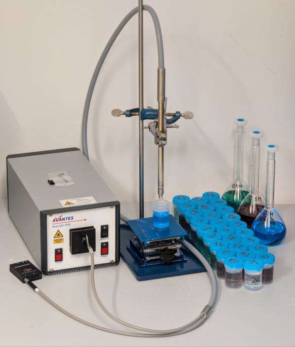
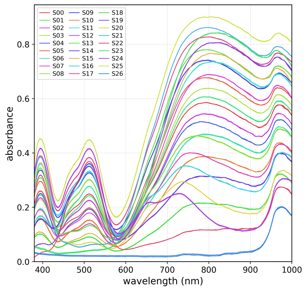
In this application note, absorbance spectra of ternary aqueous solutions of copper(II), cobalt(II) and nickel(II) nitrates were measured in the visible and short-wave near-infrared regions using a fiber-optic transflection probe (art photonics GmbH, Germany) and a compact slit-type spectrometer.
Optical Path Length: Set to 10.0 mm.
Illumination: Provided by an AvaLight-DH-S halogen light source (Avantes BV, the Netherlands).
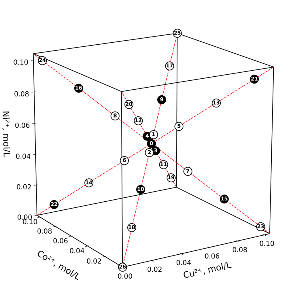
Samples: A calibration set of 27 ternary aqueous solutions (25.0 mL each) was prepared from the hydrated metal nitrates Cu(NO₃)₂·3H₂O, Co(NO₃)₂·6H₂O and Ni(NO₃)₂·6H₂O according to a diagonal experimental design.
Reference: The reference spectrum was recorded in air without a sample.
Figure 2. Diagonal experimental design for ternary aqueous mixtures of copper(II), cobalt(II) and nickel(II) nitrates [A. Bogomolov, Anal. Chim. Acta 951 (2017) 46-57]. Open and filled circles represent training and validation samples, respectively; labels indicate sample numbers.
Figure 3. Absorbance spectra of the 27 designed copper(II), cobalt(II) and nickel(II) nitrate solutions. The spectra were smoothed using the Savitzky-Golay algorithm. The three replicate spectra for each sample are plotted in the same colour.
Calibration Models
The resulting spectra were analysed, and a partial least squares regression model for multiple response variables (PLS2) was developed to determine the concentrations of all three metal ions from a single spectrum of an unknown mixture.
Five latent variables (LVs) were required to obtain accurate and robust calibration models for all three metal ions:
Three LVs were associated with variations in metal concentrations.
Two LVs may be related to weak spectral effects known to arise from metal-nitrate interactions and salt-induced changes in the water absorption band near 970 nm.
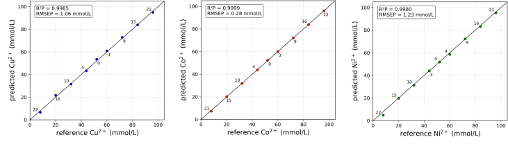
Figure 4. Predicted versus reference concentrations for Cu²⁺ (top), Co²⁺ (middle) and Ni²⁺ (bottom) in the validation set obtained with the five-latent-variable PLS2 model.
Results and Conclusion
The proposed method enables simultaneous determination of copper(II), cobalt(II) and nickel(II) from a single spectrum recorded over the 380-1000 nm range. Simultaneous determination was achieved over concentration ranges of up to approximately 0.10 mol/L (100 mmol/L or 0.6% m/v), with prediction errors of approximately 0.3-1.2 mmol/L.
The obtained results point to the possibility of achieving low detection limits for all three analytes. The broad working range and high prediction accuracy make the method suitable for various practical applications. The proposed approach can be implemented as a compact optical system for rapid field analysis and wastewater monitoring, as well as for in-line process analysis in industrial and biotechnological applications.
We are happy to welcome Joachim Gerike to the art photonics GmbH team as our new Product Line Manager.
With a Dipl.-Ing. in Mechanical Engineering from Technische Universität Braunschweig and a career in the optical industry dating back to 1996, Joachim brings decades of highly specialized expertise to our operations.
His extensive background covers everything from medical operating microscopes for surgical applications to camera-controlled packaging systems for the pharmaceutical industry, including leadership experience as Head of a Business Unit for medical applications.
At art photonics GmbH, Joachim will act as a bridge connecting our advanced fiber optics solutions to entirely new market segments. His strategic focus will be guiding our innovations from customized R&D projects into scalable, reliable serial production.
Armed with deep knowledge of the medical device industry and sharp sales strategies, friends of him describe his approach perfectly: "Der Möglichmacher" (The one who makes things happen).
Please join us in welcoming Joachim to the team. We are excited for the impact his experience and drive will bring.
When your research or production takes you into extreme environments, maintaining perfect optical transmission should never be a hurdle.
At art photonics GmbH, we invite you to explore our FlexiRay® Vacuum Fiber Optic Feedthroughs - engineered to provide a highly flexible, continuous optical path directly into your vacuum or pressurized chambers.
Whether you are conducting Mid-IR spectroscopy, flexible IR pyrometry, or routing power for Quantum Cascade lasers, our feedthrough assemblies are designed to be the preferred choice for advanced optical engineering.
Here is what makes our solution stand out:
Continuous Fiber Path (No Intermediate Splices): Say goodbye to the high coupling losses associated with traditional split setups. Our unique single-piece design allows the entire cable to pass directly through the flange without an intermediate repeater. This ensures excellent, uninterrupted signal throughput from the source directly to your sample.
Exceptionally Low Leak Rate: Reliability is critical in vacuum environments. Our feedthroughs are Helium leak-tested to perform below detection limits (better than 5x10⁻¹² mbar*l/s). The system confidently handles pressures ranging from 10 Bar down to 10⁻⁷ Torr.
Wide Temperature Tolerance: Built for environmental extremes, these feedthroughs support cryogenic applications operating down to 2K, as well as high-temperature setups reaching up to 600°C when utilizing our specialized Cu-coated silica fibers.
Mid-IR and Laser Power Delivery: Seamlessly route light and laser power across the entire 0.2 to 18 µm spectrum. Our assemblies are available with Silica, PIR, CIR, and Fluoride glass fibers to perfectly match your specific wavelength requirements.
Standard KF/CF Flanges & Adjustable Cable Length: Designed for seamless integration, our feedthroughs fit any requested flange type, including standard KF and CF flanges. Furthermore, the movable cable design allows you to adjust the exact length needed inside your chamber for ultimate installation flexibility.
Are you still waiting on offline lab samples when an in-line ATR probe could give you real-time process control?
Transitioning from offline sampling to real-time monitoring remains one of the most significant bottlenecks in Process Analytical Technology (PAT) today. At art photonics GmbH, our FlexiSpec® ATR Probes are engineered to eliminate that delay entirely, bringing the laboratory directly to your production line.
We do not simply build probes; we provide the fiber optic bridge between your spectrometer and your process. By enabling direct, in-situ measurements, we empower engineers to capture crucial spectral data exactly when it matters—in real-time.
Engineered for Harsh Environments
Industrial applications require rugged, uncompromising solutions. Designed to operate under the most demanding conditions, our ATR probes deliver continuous reliability without sacrificing analytical precision.
Key features of the FlexiSpec® lineup include:
Temperature resistance ranging from -150°C to +250°C
Pressure tolerance up to 200 Bar (with up to 300 Bar available upon request)
A specialized "No Dead Zone" design, perfectly optimized for continuous liquid flow
Complete compatibility with FT-IR, FT-NIR, and any standard benchtop devices
Broad Industry Applications
Whether your facility is tracking volatile solvent composition, monitoring complex polymerizations, or controlling precise biopharma crystallization processes, our in-line probes seamlessly integrate into your workflow to prevent downtime and optimize yield.
Explore the full capabilities of our technology and find the right fit for your facility by reviewing our complete ATR probe lineup.
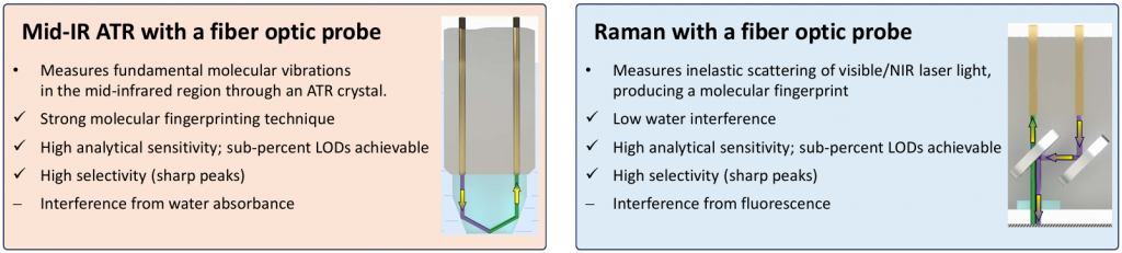
Mid-infrared (mid-IR) and Raman techniques are complementary vibrational spectroscopy methods utilized extensively in Process Analytical Technology (PAT). While both probe molecular vibrations, they rely on fundamentally different optical effects: mid-IR ATR detects the absorption of mid-IR radiation, whereas Raman relies on the inelastic scattering of visible or near-infrared (NIR) laser light.
For system integration in continuous manufacturing or batch processing, selecting the correct fiber-optic probe requires evaluating the chemical matrix, physical media constraints, and target molecular species.
Mid-IR ATR Spectroscopy: Ideal for Polar Bonds Detection
Mid-IR absorption requires a fundamental vibration that induces a change in the molecule's dipole moment. Consequently, mid-IR ATR yields high analytical sensitivity for polar bonds, producing strong, well-resolved absorption bands for functional groups such as C=O, O-H, N-H, and C-O.
In a fiber-optic Attenuated Total Reflection (ATR) probe, radiation propagates through specialty optical fibers to an ATR crystal in direct contact with the reaction medium. Internal reflection within the crystal generates an evanescent field that decays exponentially, limiting the penetration depth to approximately 0.5 - 2 µm into the sample.
Technical Parameters & System Integration:
Media Compatibility: Because the measurement is confined to the immediate 0.5 - 2 µm contact layer, the technique is robust in turbid, highly scattering, bubbly, or particle-laden media. Optical contact with the crystal must be maintained.
Reaction Tracking: Mid-IR effectively tracks functional-group chemistry in real time, yielding direct kinetic data for esterification, hydrolysis, oxidation/reduction, amide/peptide formation, and polymerization.
Water Interference: Aqueous matrices present heavy absorbance interference, though the inherently short pathlength of the ATR crystal makes measurement in aqueous media practical.
Transmission Limits: Fiber attenuation limits cable lengths to 2-3 m when utilizing standard FTIR spectrometers. Lengths can be extended up to 10 m when integrated with high-power quantum cascade laser (QCL) sources or dual-comb spectrometers.
Spectral Range: Configurations capture the fingerprint region (600-3100 cm⁻¹) as well as high-wavenumber regions (1550-9000 cm⁻¹), depending on the specific ATR crystal and fiber material.
Raman Spectroscopy: Molecule Polarizability
Raman spectroscopy characterizes vibrational levels through inelastic scattering. A monochromatic laser (typically 532 nm, 785 nm, or 1064 nm) irradiates the sample, and scattered photons undergo a detectable energy shift (the Raman shift) corresponding to a vibrational frequency. A vibration is Raman-active only if it alters the molecule's polarizability.
This fundamental difference means symmetric and non-polar bonds - such as C=C, S-S, and aromatic rings - that are weak or silent in mid-IR yield sharp, high-intensity Raman peaks.
Technical Parameters & System Integration:
Aqueous Media: Raman's primary advantage in process monitoring is its exceptionally weak water scattering cross-section, making it the superior architecture for monitoring aqueous solutions.
Signal Optimization & Wavelength Dependency: The Raman scattering cross-section scales as λ/4. Excitation at 532 nm yields higher signal strength and spatial resolution but heavily increases fluorescence interference. Shifting to 785 nm or 1064 nm suppresses background fluorescence at the expense of absolute signal intensity.
Optical Constraints: Probe length is strictly limited by free-space beam divergence; for a standard 12 mm outer diameter probe, lengths exceeding 200-300 cm are optically challenging.
Fiber Transmission: Because the signals exist in the visible/NIR spectrum, low-loss silica fibers can be utilized, allowing for cable lengths spanning tens of meters from probe to spectrometer.
Spectral Range: Standard fiber-optic Raman probes cover 130-4000 cm⁻¹, with specialized configurations achieving measurements down to 25 cm⁻¹ (THz Raman) - accessing low-frequency modes that mid-IR fiber systems physically cannot reach.
Sample Limitations: The focused laser introduces thermal risks, potentially causing photodegradation or burning in dark, highly absorbing samples. Scattering losses from bubbles or suspended particles also constrain the signal-to-noise ratio.
Complementary Solution Architecture
Mid-IR ATR and Raman fiber-optic spectroscopies operate as complementary, not competing, techniques. Deploying both ATR and Raman probes in parallel within a unified process analytical framework ensures that polar, non-polar, aqueous, and solid-phase parameters are captured entirely, preventing the diagnostic blind spots inherent to relying on a single modality.
Learn more about optimizing fiber-optic system architecture for your specific application at artphotonics.com.
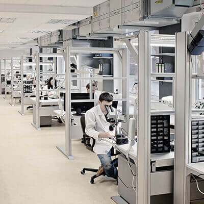
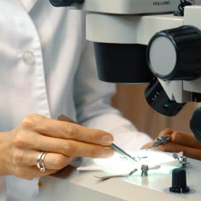
Every fiber, cable, and probe that leaves our Berlin facility gets put under a microscope. Literally.
Before a product ships, we inspect the fiber end faces for cracks and contamination, check core/clad geometry, and verify transmission against spec. On mid-IR assemblies, that means confirming losses stay within 0.2–0.3 dB/m in the 9–13 µm range — a number that only holds if every step upstream, from fiber draw to final assembly, was done right. It's slow, it's manual, and it's the reason our fibers perform exactly as the datasheet says they will.
Made in Germany, from raw fiber to finished part
That inspection work happens in-house, in Germany, under ISO 9001 — and has for over 25 years. We draw the fiber, build the cables and probes, and test them all under one roof. Nothing gets waved through on the strength of a supplier's word, because there's no external supplier in the chain to take on faith.
Where standard fiber runs out
Our real point of difference is the mid-IR. Beyond roughly 2.5 µm, standard silica fiber stops transmitting altogether. Our patented polycrystalline silver-halide (PIR) fibers carry light out to 18 µm, making them one of the few fiber options that are flexible, non-toxic, and non-hygroscopic at those wavelengths. That's what allows us to cover 200 nm to 18 µm — UV through mid-IR — from a single manufacturer:
Specialty fibers: silica, chalcogenide, and polycrystalline silver halide
Custom fiber optic cables and laser delivery assemblies
Fiber bundles for imaging, illumination, and light delivery
ATR, transflection, and Raman probes for in-line process control
Built for where the measurement actually happens
Our probes are designed for the harder end of the job — reactors, pipelines, and aggressive chemistry — for applications where it makes more sense to bring the spectrometer to the sample than the sample to the lab. That's why they're widely used in biopharma, chemical and petrochemical processing, and environmental monitoring, wherever real-time, in-line analysis has to hold up under demanding process conditions.
If you're working on a mid-IR measurement that standard silica can't handle, that's exactly the problem we specialize in solving. Get in touch, or browse our product range to see what's possible.
You are currently viewing a placeholder content from Turnstile. To access the actual content, click the button below. Please note that doing so will share data with third-party providers.